Three-Phase Induction Motor – Construction, Working, Types and Applications
What is a 3-Phase Induction Motor?
A three phase induction motor is a type of AC induction motors which operates on three phase supply as compared to the single phase induction motor where single phase supply is needed to operate it. The three phase supply current produces an electromagnetic field in the stator winding which leads to generate the torque in the rotor winding of three phase induction motor having magnetic field.
Construction of Three-Phase Induction Motor

The construction of an induction motor is very simple and robust. It has mainly two parts;
- Stator
- Rotor
Stator
As the name suggests, the stator is a stationary part of the motor. The stator of the induction motor consists of three main parts;
- Stator Frame
- Stator Core
- Stator Winding
Stator Frame
The stator frame is the outer part of the motor. The function of the stator frame is to provide support to the stator core and stator winding.
It provides mechanical strength to the inner parts of the motor. The frame has fins on the outer surface for heat dissipation and cooling of the motor.
Stator Core
The function of the stator core is to carry the alternating magnetic flux which produces hysteresis and eddy current loss. To minimize these losses, the core is laminated by high-grade steel stampings thickness of 0.3 to 0.6 mm.
These stampings are insulated from each other by varnish. All stampings stamp together in the shape of the stator core and fixed it with the stator frame.
An inner layer of the stator core has a number of slots.
Stator Winding
The stator winding is placed inside the stator slots available inside the stator core. Three-phase winding is placed as a stator winding. And three-phase supply is given to the stator winding.
The number of poles of a motor depends on the internal connection of the stator winding and it will decide the speed of the motor. If the number of poles is greater, the speed will less and if the number of poles is lesser than the speed will high. The poles are always in pairs. Therefore, the total number of poles always an even number. The relation between synchronous speed and number poles is as shown in the below equation,
NS = 120f / P
Where;
- f = Supply Frequency
- P = Total Number of Poles
- Ns = Synchronous Speed
As the end of winding connected to the terminal box. Hence, there are six terminals (two of each phase) in the terminal box.
According to the application and type of starting methods of motors, the stator winding is connected in star or delta and it is done by the connection of terminals in the terminal box.

Rotor
As the name suggests, the rotor is a rotating part of the motor. According to the type of rotor, the induction motor is classified as;
- Squirrel Cage Induction Motor
- Phase Wound (Wound Rotor) Induction motor / Slip-ring Induction Motor
The construction of the stator is same in both types of induction motors. We will discuss the types of rotors used in 3-phase induction motors in the following section of types of three phase induction motors.
 Types of Three Phase Induction Motors
Three phase motors are classified mainly in two categories based on the rotor winding (Armature coil winding) i.e. squirrel cage and slip ring (wound rotor motor).
- Squirrel Cage Induction Motor
- Slip-ring or Wound Rotor Induction Motor
Related Post: Brushless DC Motor (BLDC) – Construction, Working Principle & Applications
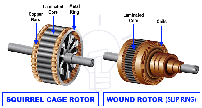
Squirrel Cage Induction Motor
The shape of this rotor is resembling the shape of the cage of a squirrel. Therefore, this motor is known as a squirrel cage induction motor.
The construction of this type of rotor is very simple and rugged. So, almost 80% of the induction motor is a squirrel cage induction motor.
The rotor consists of a cylindrical laminated core and has slots on the outer periphery. The slots are not parallel but it is skewed at some angle. It helps to prevent magnetic locking between the stator and rotor teeth. It results in smooth operation and reduces the humming noise. It increases the length of the rotor conductor due to this the rotor resistance is increased.
The squirrel cage rotor consists of rotor bars instead of the rotor winding. The rotor bars are made up of aluminum, brass, or copper.
Working Principle of Three-Phase Induction Motor
The stator winding is overlapped at 120˚ (electrically) to each other. When a three-phase supply is given to the stator winding, the rotating magnetic field (RMF) induced in the stator circuit.
The speed of the rotating magnetic field is known as synchronous speed (NS).
According to Faraday’s law, EMF induced in the conductor due to the rate of change of flux (dΦ/dt). The rotor circuit cut the stator magnetic field and an EMF induced in the rotor bar or rotor winding.
The rotor circuit is a close path. So, due to this EMF current will flow through the rotor circuit.
Now, we know that the current-carrying conductor induces the magnetic field. So, the rotor current induces a second magnetic field.
The relative motion between the stator flux and rotor flux, the rotor starts to rotate to reduce the cause of relative motion. The rotor tries to catch the stator flux and starts rotating.
The direction of rotation is given by the Lenz’s law. And is in the direction of the rotating magnetic field induced by the stator.
Here, the rotor current is produced due to inductance. Therefore, this motor is known as the induction motor.
The speed of the rotor is less than the speed of synchronous speed. The rotor tries to catch the rotating magnetic field of the stator. But it never catches it. Hence, the speed of the rotor is slightly less than the speed of synchronous speed.
The synchronous speed depends on the number of poles and supply frequency. The difference between the actual speed of the rotor and synchronous speed is known as slip.


Comments
Post a Comment